Designing an 8-Bit Integer Primality Test Using Logic Circuits
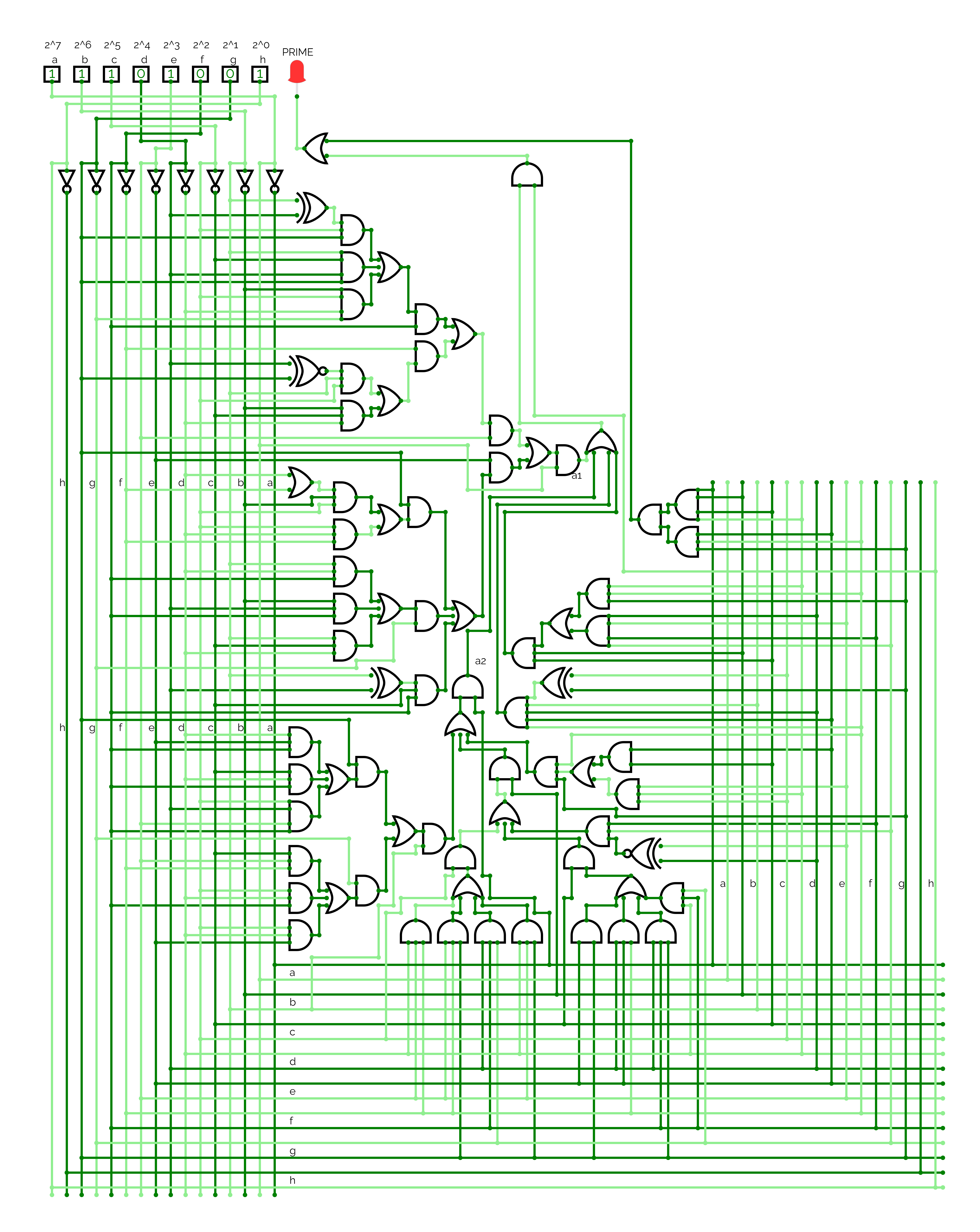
When working with digital circuits and number theory, I found that an interesting challenge is determining whether a given number is prime through purely combinational logic. Recently, I developed a circuit diagram for testing the primality of 8-bit integers using a Boolean function f(a,b,c,d,e,f,g,h).
From Truth Table to Near-Minimal Form
The process started with a comprehensive truth table that enumerated all possible 8-bit inputs (0 to 255) and flagged which of those are prime. This truth table served as the cornerstone of the design, capturing every input-to-output mapping.
An excerpt of the table is listed below
a | b | c | d | e | f | g | h | Decimal | Prime? |
|---|---|---|---|---|---|---|---|---|---|
| 0 | 0 | 0 | 0 | 0 | 0 | 0 | 0 | 0 | 0 |
| 0 | 0 | 0 | 0 | 0 | 0 | 0 | 1 | 1 | 0 |
| 0 | 0 | 0 | 0 | 0 | 0 | 1 | 0 | 2 | 1 |
| 0 | 0 | 0 | 0 | 0 | 0 | 1 | 1 | 3 | 1 |
| 0 | 0 | 0 | 0 | 0 | 1 | 0 | 0 | 4 | 0 |
| 0 | 0 | 0 | 0 | 0 | 1 | 0 | 1 | 5 | 1 |
| 0 | 0 | 0 | 0 | 1 | 0 | 1 | 1 | 11 | 1 |
| 0 | 0 | 0 | 1 | 0 | 1 | 0 | 1 | 21 | 0 |
| 0 | 0 | 1 | 0 | 0 | 1 | 0 | 1 | 37 | 1 |
| 0 | 1 | 0 | 0 | 0 | 0 | 0 | 1 | 65 | 0 |
| 0 | 1 | 0 | 0 | 1 | 0 | 0 | 1 | 73 | 1 |
| 0 | 1 | 1 | 0 | 0 | 0 | 0 | 1 | 97 | 1 |
| 1 | 0 | 0 | 0 | 0 | 0 | 0 | 1 | 129 | 0 |
| 1 | 0 | 0 | 0 | 1 | 1 | 0 | 1 | 141 | 0 |
| 1 | 0 | 1 | 0 | 1 | 0 | 1 | 1 | 171 | 0 |
| 1 | 1 | 0 | 0 | 1 | 1 | 0 | 1 | 229 | 1 |
| 1 | 1 | 1 | 0 | 0 | 0 | 1 | 1 | 227 | 1 |
| 1 | 1 | 1 | 1 | 1 | 1 | 0 | 1 | 253 | 0 |
With the initial definition in hand, I applied the Quine-McCluskey (QMC) algorithm — a classic Boolean simplification method. This gave a minimal solution in terms of prime (not related to the primality test problem which we are solving here) implicants. However, the theoretically minimal form doesn’t always translate to the most practical implementation. To address this, I performed additional algebraic factorizations, aiming to balance minimality and practical constraints like the total number of gates and propagation delay. The final result is a near-minimal form that efficiently represents the primality function.
Interactivity and Exploration
If you’re curious to see this in action, I’ve provided an interactive environment where you can experiment with the inputs and observe the outputs directly. Feel free to play around and tweak bits—try changing the inputs and see how the circuit responds. You can toggle one of the 8 bits at the top of the diagram to generate your own 8-bit integer.
Try it out here!: https://circuitverse.org/users/283769/projects/prime_number_test
Logic Circuit Diagram
The project file can be downloaded from here.

Final Thoughts
The techniques applied here — truth table construction, Quine-McCluskey minimization, and further algebraic optimization — are not limited to primality tests. They are part of the essential toolbox for digital logic design. By working through such an example, you’ll gain a deeper understanding of the trade-offs between perfect minimization and practical considerations like flexibility and ease of modification.
Note that while this approach effectively demonstrates the concept for 8-bit integers, it becomes increasingly impractical to scale for larger bit-widths (e.g., 16-bit or higher) due to the exponential growth in the truth table size and the corresponding complexity of the Boolean function. This limitation lies in the nature of prime numbers themselves, as they lack a simple, deterministic function to identify them, requiring inherently complex and resource-intensive algorithms or representations.
Enjoy Reading This Article?
Here are some more articles you might like to read next: