DIY IoT: Building a Smart Adapter Plug from Scratch with ESP8266-01 and MQTT
The ESP8266 Wi-Fi chip family, now several years old, remains a fantastic choice for DIY IoT projects. With a built-in microcontroller unit (MCU) and a full TCP/IP stack, the ESP8266 is a versatile and affordable solution for a wide range of IoT (Internet of Things) applications. Produced by the Chinese manufacturer Espressif Systems in Shanghai, these chips have become increasingly popular among hobbyists and makers.
For this post, I’m using the compact ESP8266-01 module, which provides just two general-purpose input/output (GPIO) pins. Despite its minimal pin count, the module is small, inexpensive, and perfectly suitable for the task at hand. Here, we’ll walk through the steps to build a simple adapter plug that can be turned on and off over the internet—or a local network—using an ESP8266 module and the MQTT protocol. This project serves as a clear example of how to create connected devices with minimal hardware and effort, making it a relevant and educational reference for anyone interested in IoT.
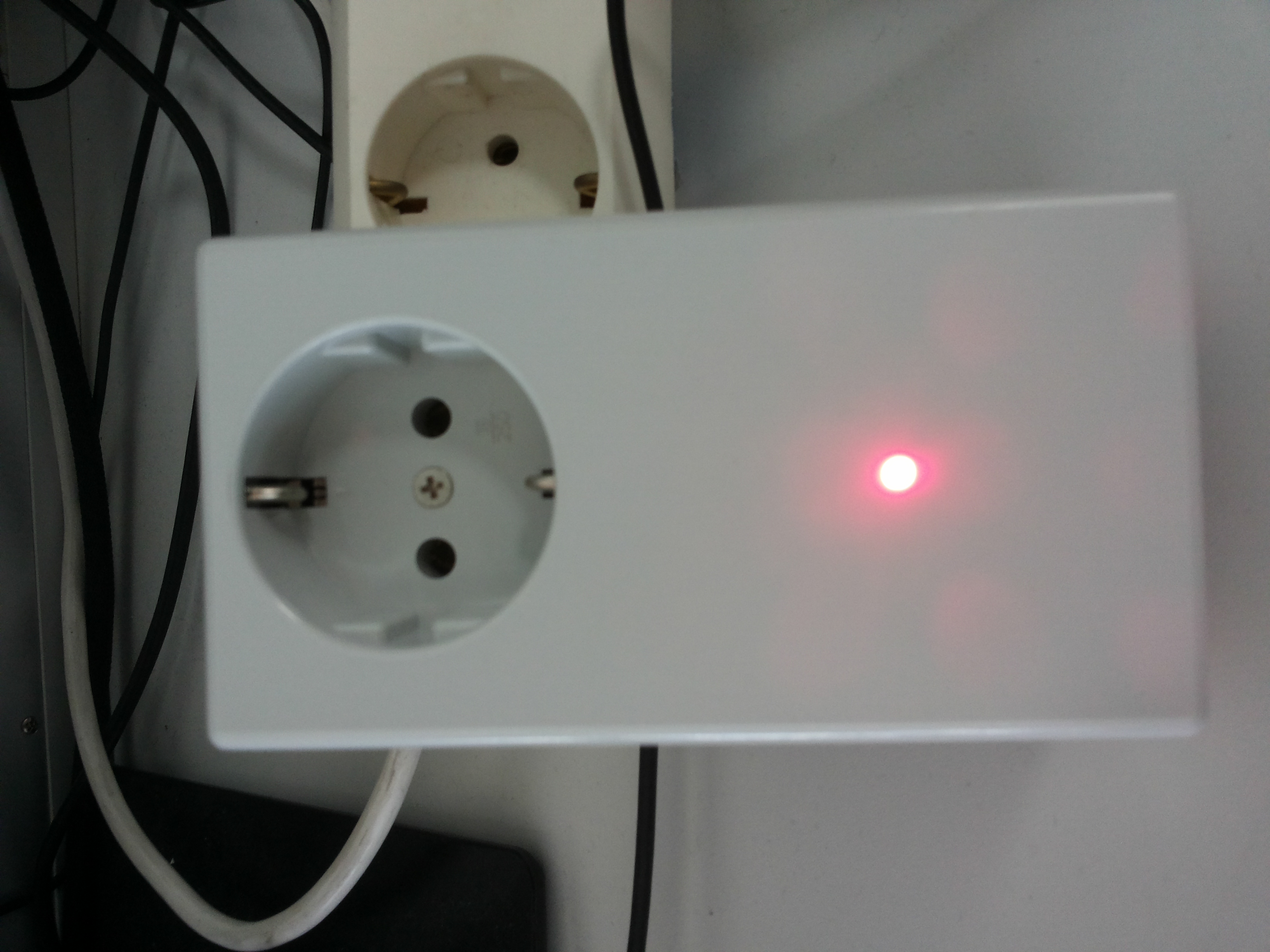
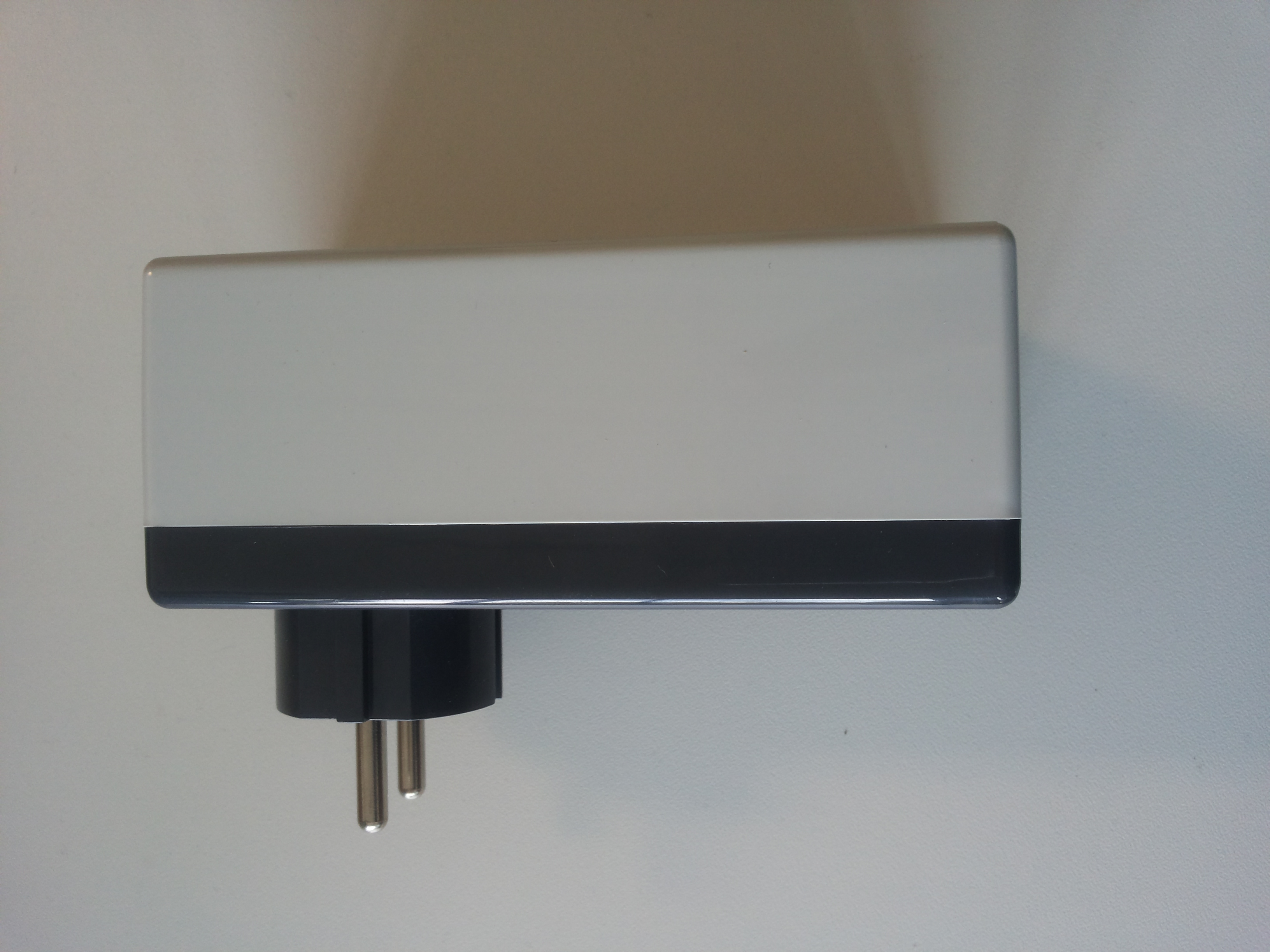
In this post, we’ll walk through the steps to build a simple adapter plug that can be controlled over the internet—or a local network—using an ESP8266 module and the MQTT protocol. The finished adapter plug will look like this:
The low-cost ESP8266 Wi-Fi chip family has become increasingly popular among hobbyists. The ESP8266 features a built-in microcontroller unit (MCU) and a full TCP/IP stack, making it an attractive choice for many IoT (Internet of Things) projects. These chips are produced by the Chinese manufacturer Espressif Systems, based in Shanghai. For this post, I am using a simple module, the ESP8266-01, which provides only two general-purpose input/output (GPIO) pins but is compact and perfectly sufficient for the task at hand. The figure below shows the top view of the ESP-01.
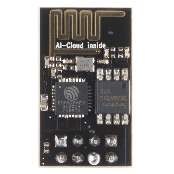
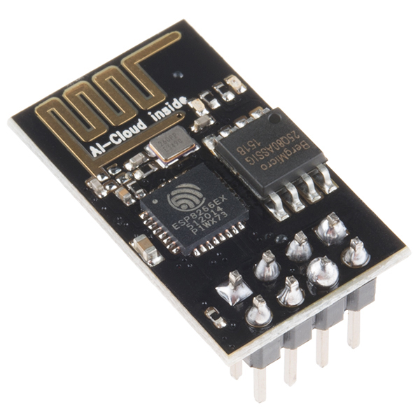
Top view of the ESP8266-01 module. Images taken from Sparkfun. Images are CC by 2.0
Wiring of the ESP8266-01
The first and most important thing to note is that the ESP8266 chip operates entirely on 3.3V for both power and I/O. Never connect it directly to 5V, as this will likely damage the chip permanently. Extra caution is required when using FTDI USB-to-TTL adapter cables, which often provide 5V on VCC.
If you are using your own power supply, ensure it can deliver at least 200mA—this applies as well to USB ports and adapter cables. Insufficient current can lead to erratic behavior, such as random restarts of the ESP.
When working with FTDI USB-to-TTL adapters that use the PL-2303HX chipset, you may encounter driver installation issues on Windows 7, 8, or 10. In my experience, the solution described at ifamilysoftware.com resolved these problems.
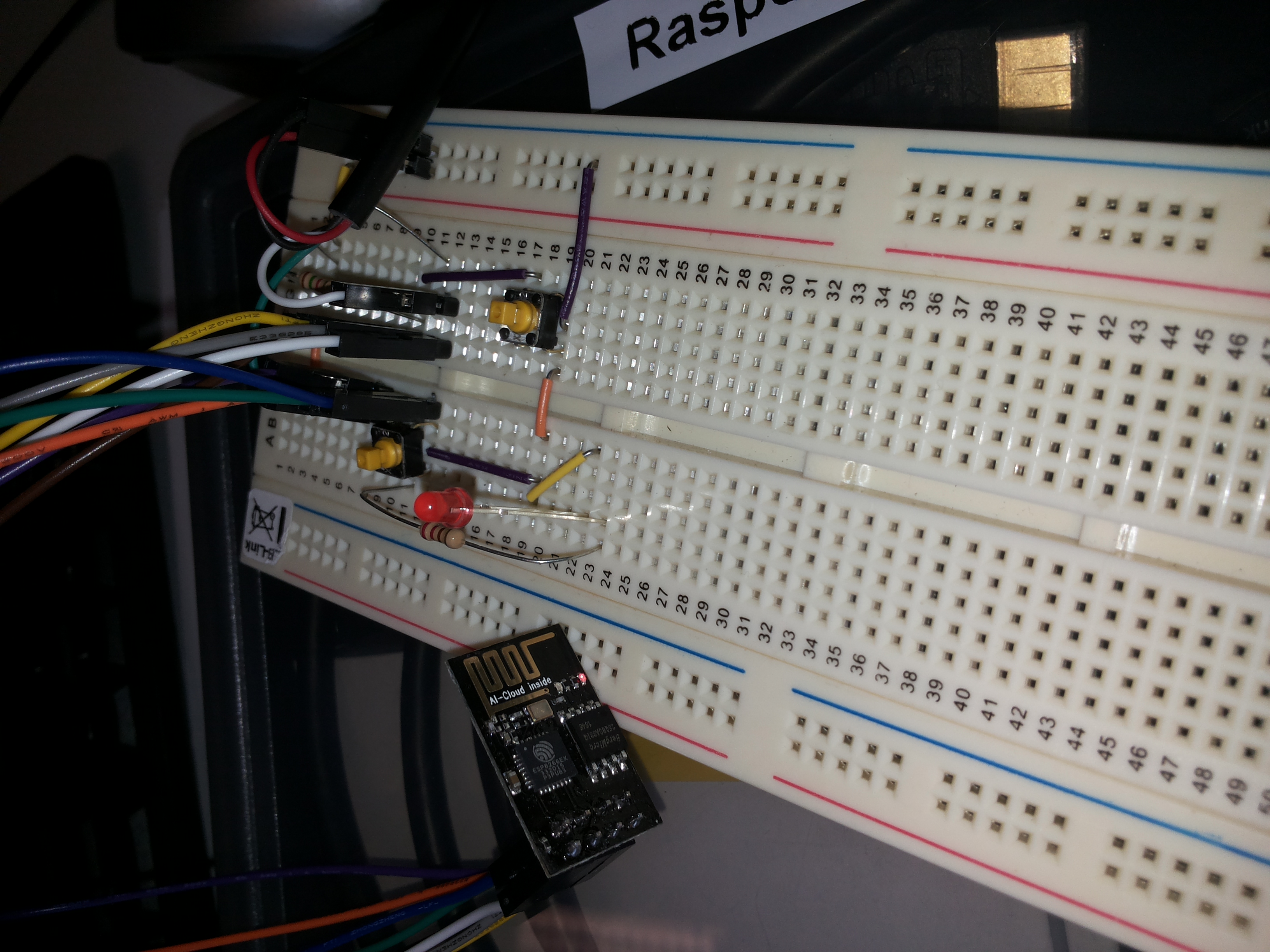
Typically, the ESP8266-01 is wired as shown in the following diagram:
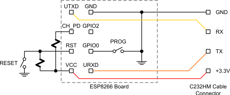
Image taken from https://www.esp8266.com/wiki/doku.php?id=getting-started-with-the-esp8266
The ESP-01 module has 8 pins: VCC, GND, CH_PD, TX, RX, RST, GPIO0, and GPIO1. To make the module work correctly, follow this wiring scheme:
- VCC: Connect to 3.3V.
- CH_PD: Must be pulled up to 3.3V, typically via a 1kΩ resistor. This step is essential; the ESP will not function without it.
- GND: Connect to the FTDI adapter’s GND pin.
- RX and TX: Required for serial communication with your computer. When connecting to the FTDI adapter, cross the wires:
- RX → FTDI TX
- TX → FTDI RX
- RST: Pull up to 3.3V with a 1kΩ resistor. Pulling it down to GND via a switch will reset the module (RESET switch in the diagram). Do not forget the pull-up resistor, or the ESP will reset continuously.
- GPIO0: Connect to GND through a switch (PROG in the diagram) to enable flashing. During normal operation, it can be used for other purposes.
- GPIO1: Free for general use.
This wiring ensures proper operation and allows you to flash and control the ESP-01 safely.
First Conversation with the ESP
To verify that your wiring with a new ESP8266-01 works, you can use a standard terminal emulator to communicate with the module, which comes with pre-flashed firmware. Note that once you flash the ESP-01 yourself, it will no longer respond to AT commands (such as AT+GMR or AT+RST), since the original firmware will be overwritten.
The ESP-01’s default baud rate is not consistent, so you may need to try different settings. Start with 9600 and 115200, then try 57600 or 76800 (38400 × 2). At the wrong baud rate, you might see garbled symbols or nothing at all.
After resetting the ESP module, a ready message should appear at the correct baud rate if your UART RX wiring is correct. Once you have identified a working baud rate, you can send the first AT command to check if the module is responsive. The module should reply with OK.
  AT

  OK
Additionally, you can try the AT+GMR command, which should produce a result similar to this:
  AT+GMR

  AT version:0.40.0.0(Aug  8 2015 14:45:58)
  SDK version:1.3.0
  Ai-Thinker Technology Co.,Ltd.
  Build:1.3.0.2 Sep 11 2015 11:48:04
  OK
The AT command set for the ESP8266 is quite extensive. A handy table of commands—including those used to configure Wi-Fi—can be found here. Even with this basic firmware installed, you can already accomplish a wide range of tasks on the ESP module.
A simple Test Program using the Arduino IDE
With just a few steps, you can use the Arduino IDE to program ESP8266 modules. Numerous tutorials are available online to guide you through setting up the Arduino IDE for the ESP8266 family.
Once your Arduino environment is set up, a great first test is a simple program that blinks an LED.
The wiring for this setup is straightforward and illustrated in the following diagram.
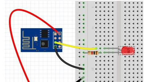
Connecting a LED to the GPIO-2 pin of the ESP8266 modul. Note that the connection diagram shown here is simplified and does not include the additional connections that are typically required (TxD, RxD) to flash a program to the device. Figure taken from iot-playground.com
To see the result, connect an LED to the GPIO-2 pin through a resistor (typically 220–330 Ω, but calculate the appropriate value for your setup) and connect the other side to ground, as shown in the diagram above. Once the wiring is complete, you can flash the ESP8266-01 with the following simple program, which will make the LED blink at short intervals.
// ESP8266-01 LED Blink Example
// This sketch blinks an LED connected to GPIO-2

const int ledPin = 2;          // Pin connected to the LED
const unsigned long ON_TIME = 500;   // LED on duration in milliseconds
const unsigned long OFF_TIME = 1000; // LED off duration in milliseconds

void setup() {
  pinMode(ledPin, OUTPUT);      // Configure the LED pin as an output
}

void loop() {
  blinkLED(ledPin, ON_TIME, OFF_TIME);
}

// Function to blink an LED with specified on/off durations
void blinkLED(int pin, unsigned long onTime, unsigned long offTime) {
  digitalWrite(pin, HIGH);      // Turn LED on
  delay(onTime);                // Wait for onTime milliseconds

  digitalWrite(pin, LOW);       // Turn LED off
  delay(offTime);               // Wait for offTime milliseconds
}
Circuit for Controlling the Adapter Plug
Once you’ve confirmed that your ESP8266 is working correctly and you’re comfortable programming it, let’s move on to the circuit for our adapter plug.
Important: If you plan to work with mains voltage, extreme caution is required. Ensure that all high-voltage contacts are properly insulated and not exposed. If you are not confident handling mains electricity, you can still build the circuit to switch lower voltages safely.
First, let’s take a look at the stripboard layout:
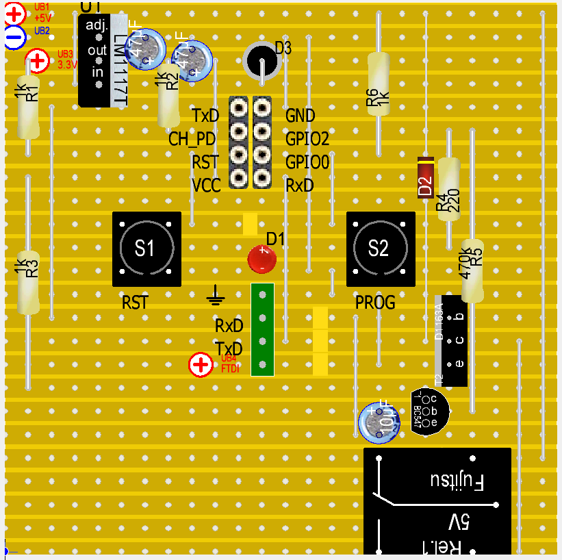
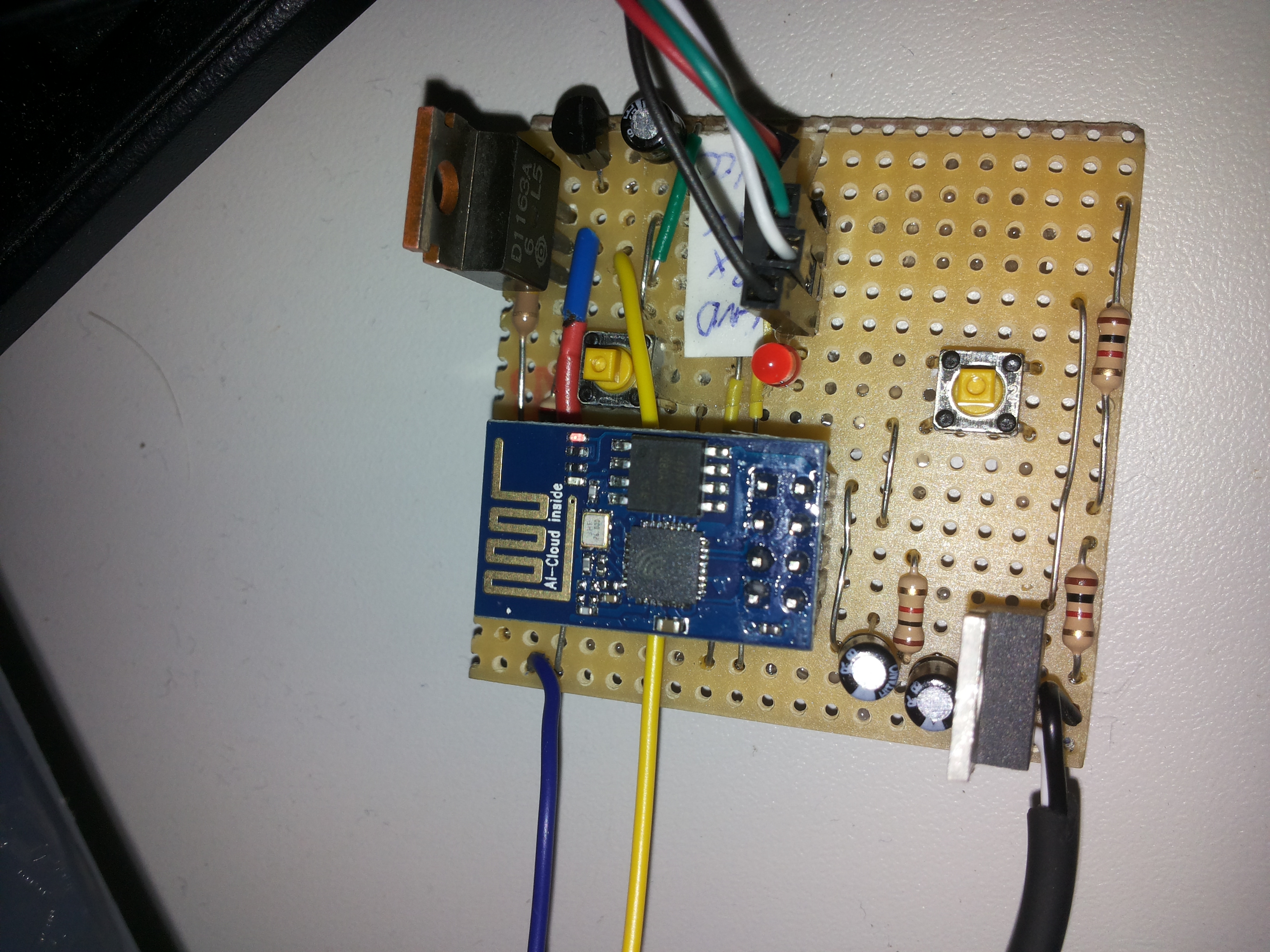
- The circuit requires a 5V supply (top-left corner of the diagram). Ensure the power source can provide at least 500 mA. I found a compact supply that fits neatly inside the adapter plug enclosure.
- Since the ESP-01 module operates at 3.3V, a voltage regulator (LM1117T) is used to step down the 5V supply.
- The ESP-01 module is plugged into the socket shown in the upper-middle part of the diagram.
- Button S1 (RST) is used to reset the ESP-01.
- Button S2 serves two purposes:
- Enter programming mode: press S1 → press S2 → release S2 → release S1.
- Normal operation: manually turn the outlet on or off.
- Transistor T2 (e.g., D1163A or equivalent) drives the relay. Any NPN transistor capable of handling the relay current can be used. A diode (D2) must be connected in parallel to the relay to protect the circuit from voltage spikes caused by the relay’s inductive load.
- LED D1 indicates the current state of the adapter plug (on or off).
- The ESP-01 cannot reliably initialize if GPIO2 is directly connected to T2’s base, likely because GPIO2 defaults to HIGH at startup and attempts to activate the relay. To prevent this, a second transistor T1 (BC547) with a 10 µF capacitor delays the HIGH signal from GPIO2 for about one second. During initialization, the capacitor charges through R5 (470 kΩ), keeping T1 inactive until the voltage is sufficient. Once T1 activates, T2 can drive the relay safely.
- The green pin header connects to an FTDI device to program the ESP-01 via the serial interface.
- The ESP-01 operates between 0 V and 3.3 V. Make sure your FTDI converter matches this voltage range to avoid damaging the module.
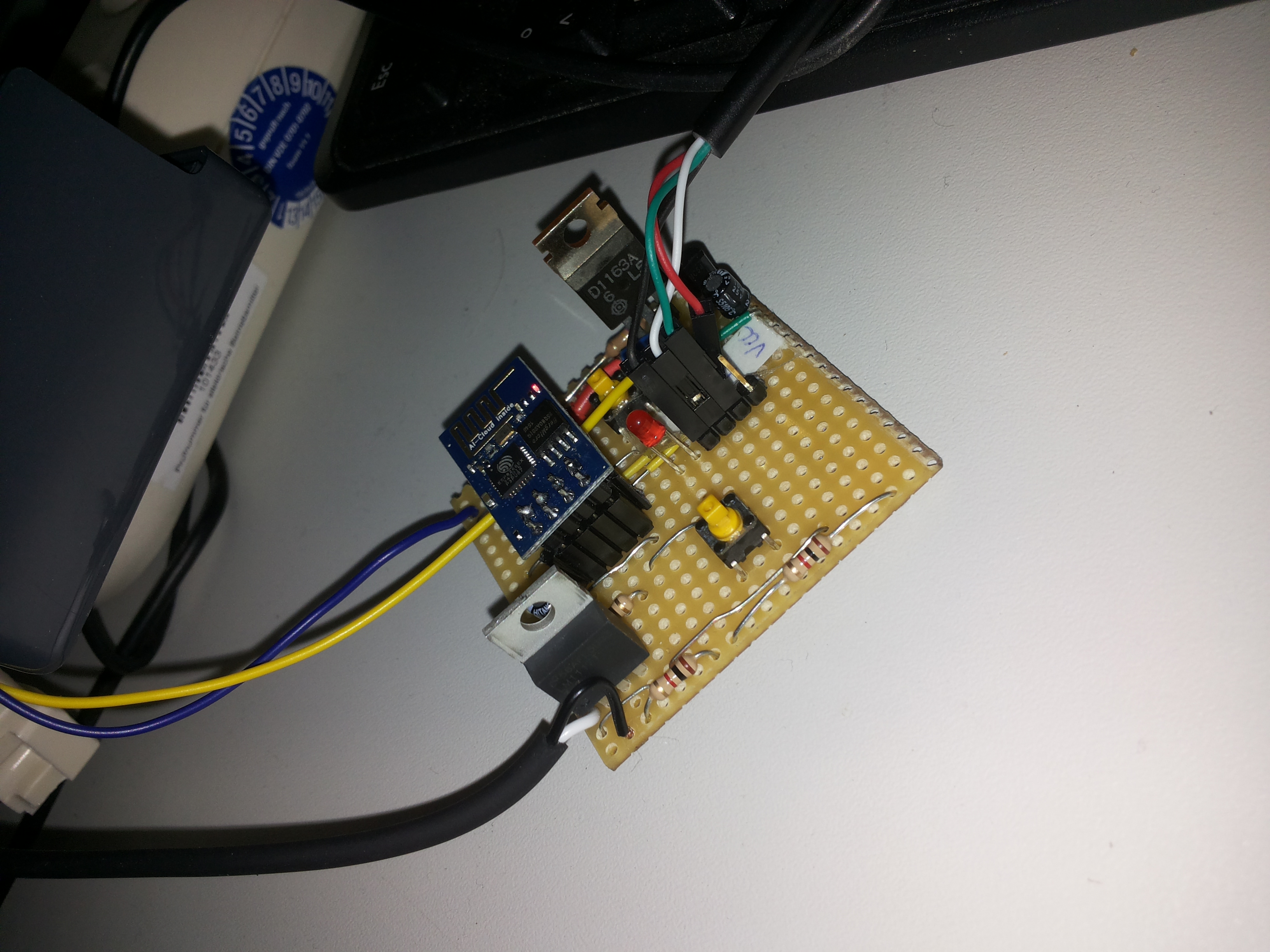
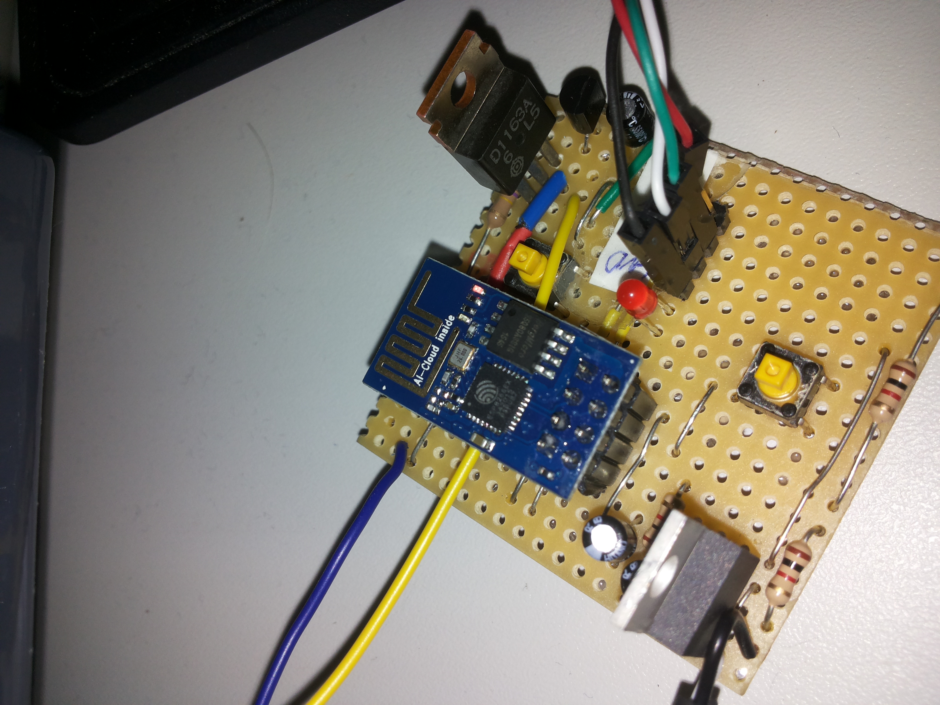
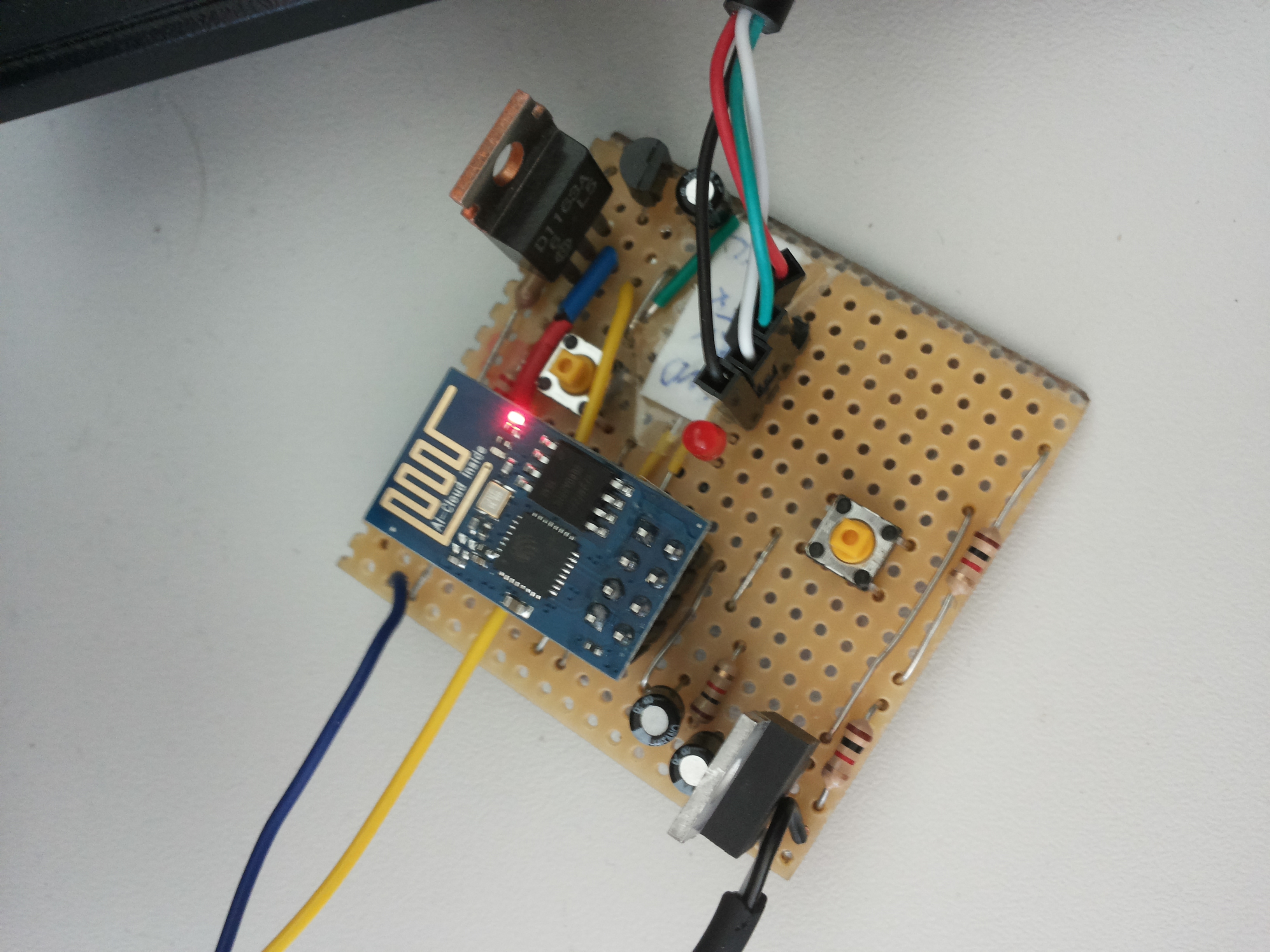
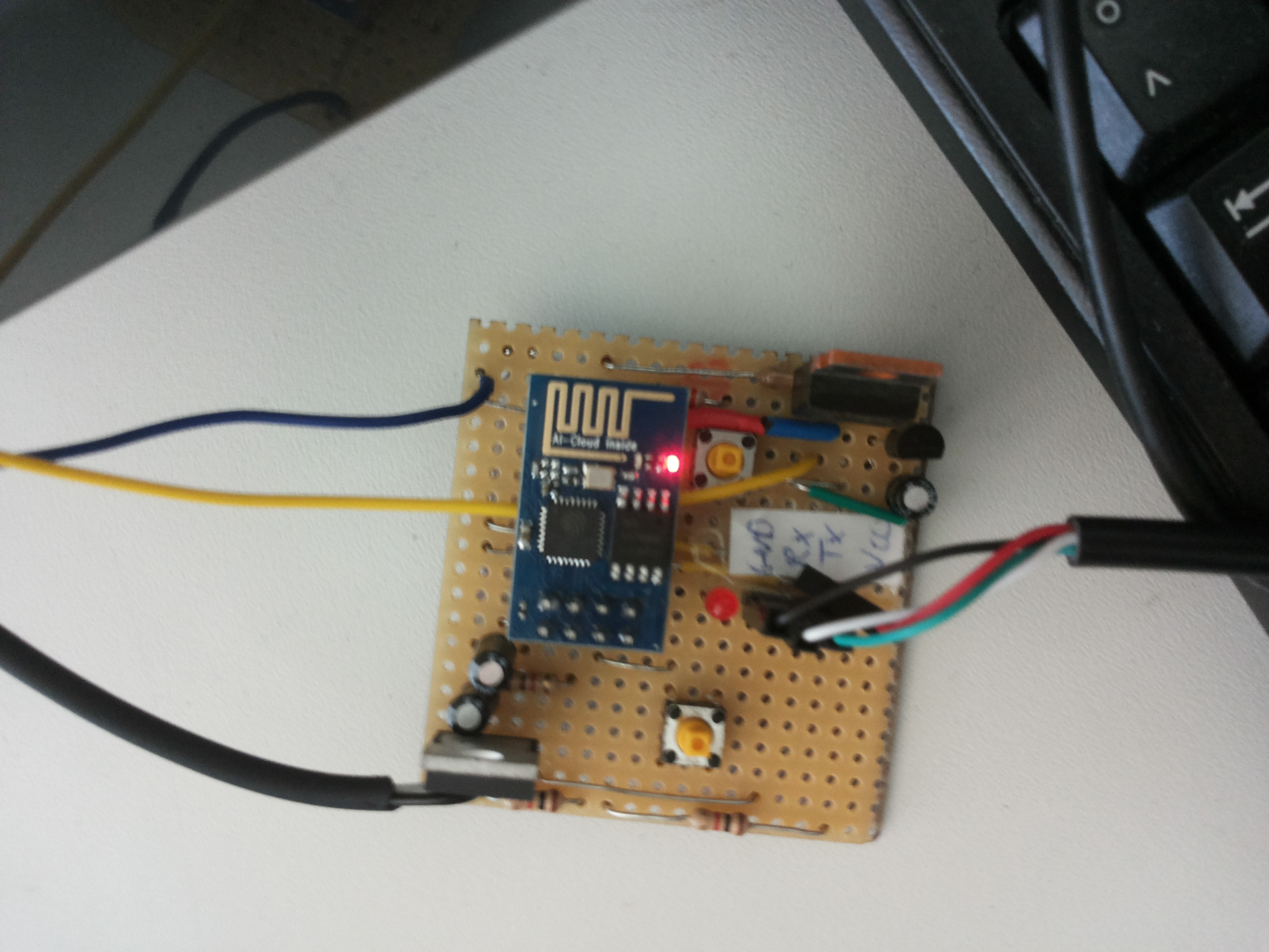
The following images show how the circuit board and the final adapter plug could look like:


Source code
Finally, we just need a program to control the adapter plug via MQTT, and the setup is complete!
#include <ESP8266WiFi.h>
#include <PubSubClient.h>
#include <string.h>

#define SLEEP_DELAY_IN_SECONDS  10
#define TOPIC_ROOT "diedackel/f"
#define DEVICE_ID  "plug-02"
#define SLASH "/"
#define CMD_RELAIS_ON "device=on"
#define CMD_RELAIS_OFF "device=off"
#define STR_CONFIRM_STATE "confirmNewState="

// ---------------------- WIFI & MQTT CONFIGURATION ----------------------
const char* ssid = "FusulFusul"; // WiFi SSID
const char* password = "";        // WiFi password
const char* mqtt_server = "io.adafruit.com";
const char* mqtt_username = "";
const char* mqtt_password = "";
const char* mqtt_pubs_topic = TOPIC_ROOT SLASH DEVICE_ID;
const char* mqtt_subs_topic = TOPIC_ROOT SLASH DEVICE_ID;

WiFiClient espClient;
PubSubClient client(espClient);

// ---------------------- GPIO & STATE VARIABLES ----------------------
int GPIO2 = 2; // GPIO pin controlling the relay
int GPIO0 = 0; // GPIO pin for manual relay control button
int state = LOW; // Current relay state
bool debounce = false; // Debounce flag for button press

/*
 * setup() - Called once during initialization after reset
 */
void setup() {
  // Configure GPIO0 as input and attach interrupt for button press
  pinMode(GPIO0, INPUT);
  attachInterrupt(GPIO0, fallingEdge, FALLING);

  // Initialize serial port for debugging
  Serial.begin(115200);

  // Connect to WiFi network
  setup_wifi();

  // Initialize MQTT client
  client.setServer(mqtt_server, 1883);
  client.setCallback(callback);

  // Configure GPIO2 as output for relay control
  pinMode(GPIO2, OUTPUT);
  //pinMode(LED_BUILTIN, OUTPUT); // Commented out: may conflict with TX/RX pins
}

/*
 * fallingEdge() - Interrupt service routine for button press
 */
void fallingEdge() {
  if (!debounce) {
    state = !state;             // Toggle relay state
    digitalWrite(GPIO2, state); // Update relay output
    debounce = true;            // Prevent multiple triggers
  }
  // Avoid calling other functions (like delay) in interrupts
}

/*
 * setup_wifi() - Connect to WiFi network
 */
void setup_wifi() {
  delay(10);
  Serial.println();
  Serial.print("Connecting to ");
  Serial.println(ssid);

  WiFi.begin(ssid, password);
  int i = 0;
  while (WiFi.status() != WL_CONNECTED && i++ < 10) {
    delay(500);
    Serial.print(".");
  }

  Serial.println("");
  Serial.println("WiFi connected");
  Serial.println("IP address: ");
  Serial.println(WiFi.localIP());
}

/*
 * callback() - MQTT callback function triggered when a message arrives
 * @topic: Topic on which the message was received
 * @payload: Message payload
 * @length: Length of payload
 */
void callback(char* topic, byte* payload, unsigned int length) {
  char msg[50];
  int i;
  char string[50];
  char lowerString[50];

  sprintf(msg, "Message arrived [%s] ", topic);
  Serial.println(msg);

  // Copy payload into C-string and convert to lowercase
  for (i = 0; i < length; i++) {
    string[i] = (char)payload[i];
    lowerString[i] = tolower(string[i]);
  }
  string[i] = 0;
  lowerString[i] = 0;
  Serial.println(lowerString);

  // Determine if payload is a known command
  uint8_t newState = -1;
  if (strcmp(lowerString, CMD_RELAIS_ON) == 0)
     newState = HIGH;
  else if (strcmp(lowerString, CMD_RELAIS_OFF) == 0)
     newState = LOW;

  // Apply new relay state if valid
  if (newState == LOW || newState == HIGH) {
    state = newState;
    digitalWrite(GPIO2, state);

    // Send confirmation message via MQTT
    sprintf(msg, "%s%d", STR_CONFIRM_STATE, state);
    Serial.println(msg);
    client.publish(mqtt_pubs_topic, msg);
  }

  Serial.println();
}

/*
 * reconnect() - Reconnect to MQTT broker if connection is lost
 */
void reconnect() {
  int i = 0;
  while (!client.connected() && i++ < 10) {
    Serial.println("Attempting MQTT connection...");
    if (client.connect(DEVICE_ID, mqtt_username, mqtt_password)) {
      Serial.println("connected");

      // Subscribe to the topic for incoming commands
      if(client.subscribe(mqtt_subs_topic))
        Serial.println("Subscribed to the specified topic");
      else
        Serial.println("Failed to subscribe to the specified topic");

      // Publish an initial message
      client.publish(mqtt_pubs_topic, "Hello, here I am...");
    } else {
      Serial.print("failed, rc=");
      Serial.print(client.state());
      Serial.println(" trying again in 500 milliseconds");
      delay(500);
    }
  }
}

/*
 * loop() - Main loop function, repeatedly called after setup()
 */
void loop() {
  static int loopCounter = 0;
  loopCounter++;
  char msg[50];

  // Reconnect WiFi if disconnected
  if (WiFi.status() != WL_CONNECTED) {
    setup_wifi();
  }
  // Reconnect MQTT if disconnected
  else if (!client.connected()) {
    reconnect();
  }

  // Print a periodic "still alive" message every ~minute
  if(loopCounter % 200 == 0) {
    Serial.println("I am still alive...");
  }

  // Process MQTT messages
  client.loop();
  delay(300);

  // Publish current relay state if button was pressed or periodically
  if (client.connected() && (debounce || loopCounter % 200 == 0)) {
    sprintf(msg, "%s%d", STR_CONFIRM_STATE, state);
    client.publish(mqtt_pubs_topic, msg, true); // retained message
  }

  // Reset debounce flag after processing
  debounce = false;
}
Usage
Once the ESP-01 is flashed with the program above, there are two ways to control the electrical outlet:
-
Manual Control: Use button S2 to toggle the outlet. Each press of the button will invert the current state of the relay.
-
MQTT Control: Use an MQTT client to publish messages to the configured topic to turn the outlet on or off. For example (based on the definitions in the code above, though some adjustments may be needed), you can send the following messages:
MQTT-Broker:        iot.eclipse.org
Port:               1883
Topic:              my-mqtt-topic/plug-01
Accepted Messages:  DEVICE=ON
                    DEVICE=OFF
Future Work
While this prototype is already functional, there are several improvements and extensions that could make it even more versatile:
- Query the outlet state via MQTT: Allow clients to request the current state of the relay at any time.
- Use a bi-stable relay: This would reduce power consumption and put less strain on the power supply compared to a standard relay.
- Advanced addressing and communication: Develop a more robust scheme for managing multiple outlets or more complex setups.
- Smartphone app integration: Create an app to control the outlets and other MQTT-enabled devices easily.
- Integration with smart home systems: Connect the adapter plug to broader smart home platforms for centralized management and automation.
Conclusion
In this project, we built a fully functional IoT adapter plug using the compact ESP8266-01 module. The key features include manual control via a push button and remote control via MQTT messages, making it a flexible solution for home automation. We walked through the main steps: wiring the ESP-01 and relay circuit, setting up the Arduino IDE, programming the ESP, and connecting it to WiFi and an MQTT broker. This project demonstrates how even minimal hardware can be used to create smart, networked devices, and provides a foundation for further enhancements like energy-efficient relays, smartphone apps, and integration with larger smart home systems.
Enjoy Reading This Article?
Here are some more articles you might like to read next: